must produce high torque while remaining compact, backdrivable,
and safe to interact with. Elastic actuators meet these
needs by placing a compliant element between the drivetrain
and the load and inferring torque from its deflection, but
trade bandwidth for force-control fidelity. A differential elastic
actuator (DEA) is a variant of elastic actuator in which the
spring grounds one port of a differential transmission, so that
output torque can be read from a single static, housing-mounted
encoder. We present a DEA based on a harmonic drive and
sprung ring gear, with a novel arcuate spring geometry shaped
by an equal-stress optimization. By wrapping the spring around
our high-torque transmission, we create a torque-dense actuator
with high-fidelity force control and acceptable bandwidth for
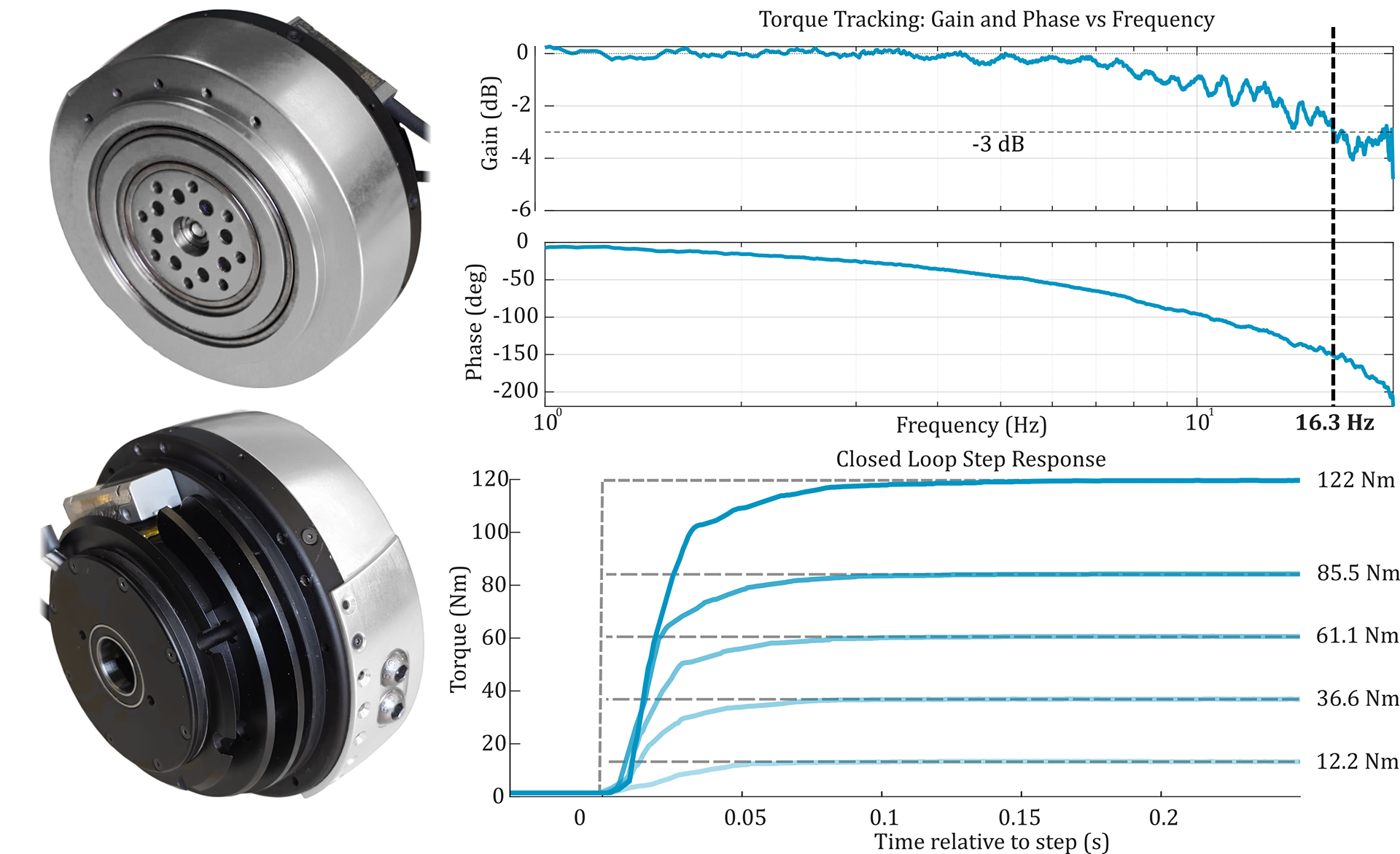
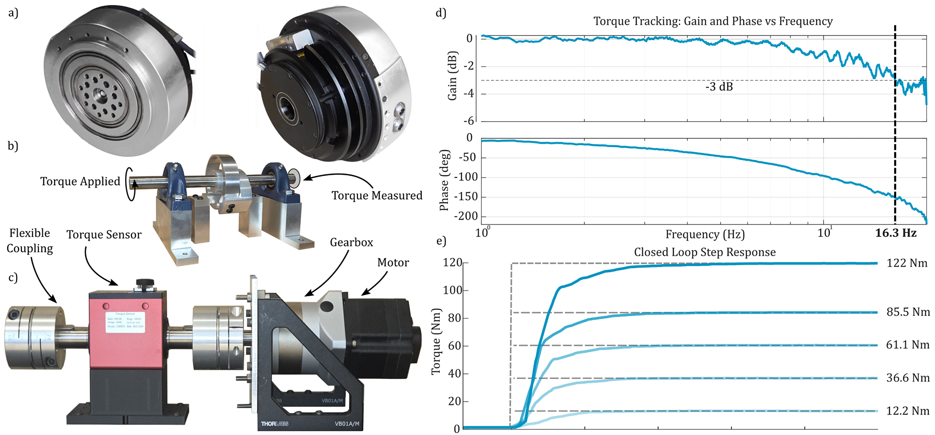
lower-limb actuation. Our actuator achieves a peak torque of
122 Nm at a mass of 980 g, a torque-tracking bandwidth of
16.3 Hz, and holds backdrive torque under 3 Nm against output
disturbances up to 9 Hz, the limit of our test rig.
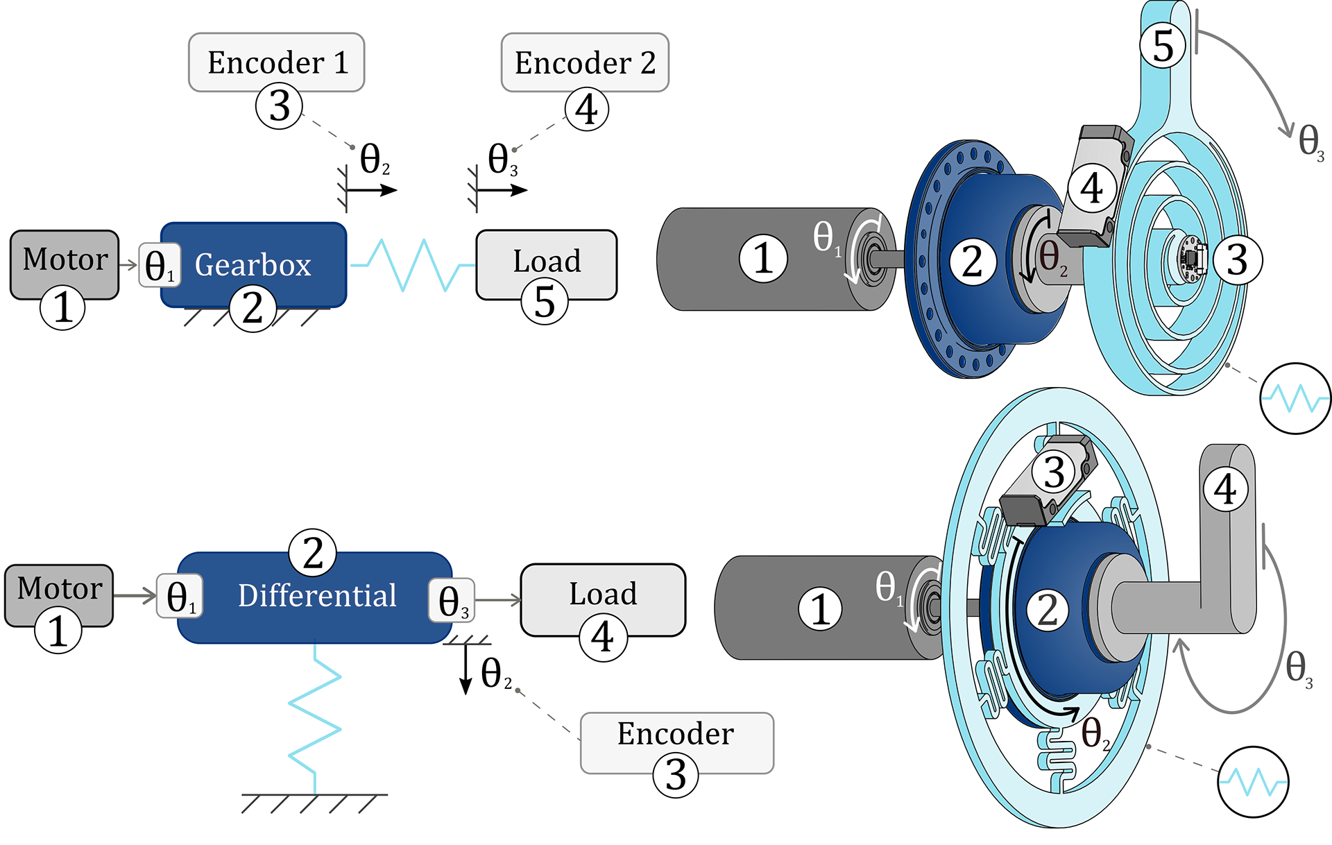
Series versus differential elastic actuation, with corresponding
numbers to mark important components labeled in the block diagrams. In the SEA the spring sits in the load path; in the DEA the spring grounds the circular spline, so a single static encoder reads transmission rotation as spring deflection.
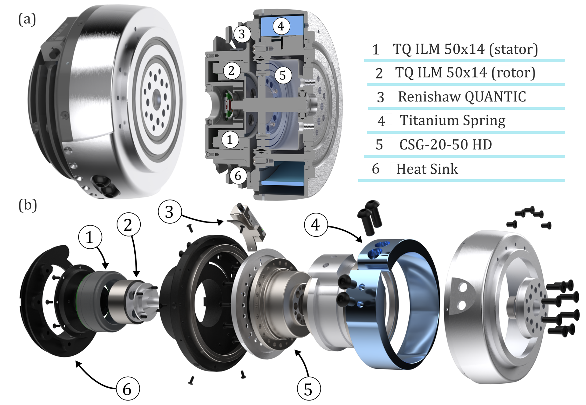
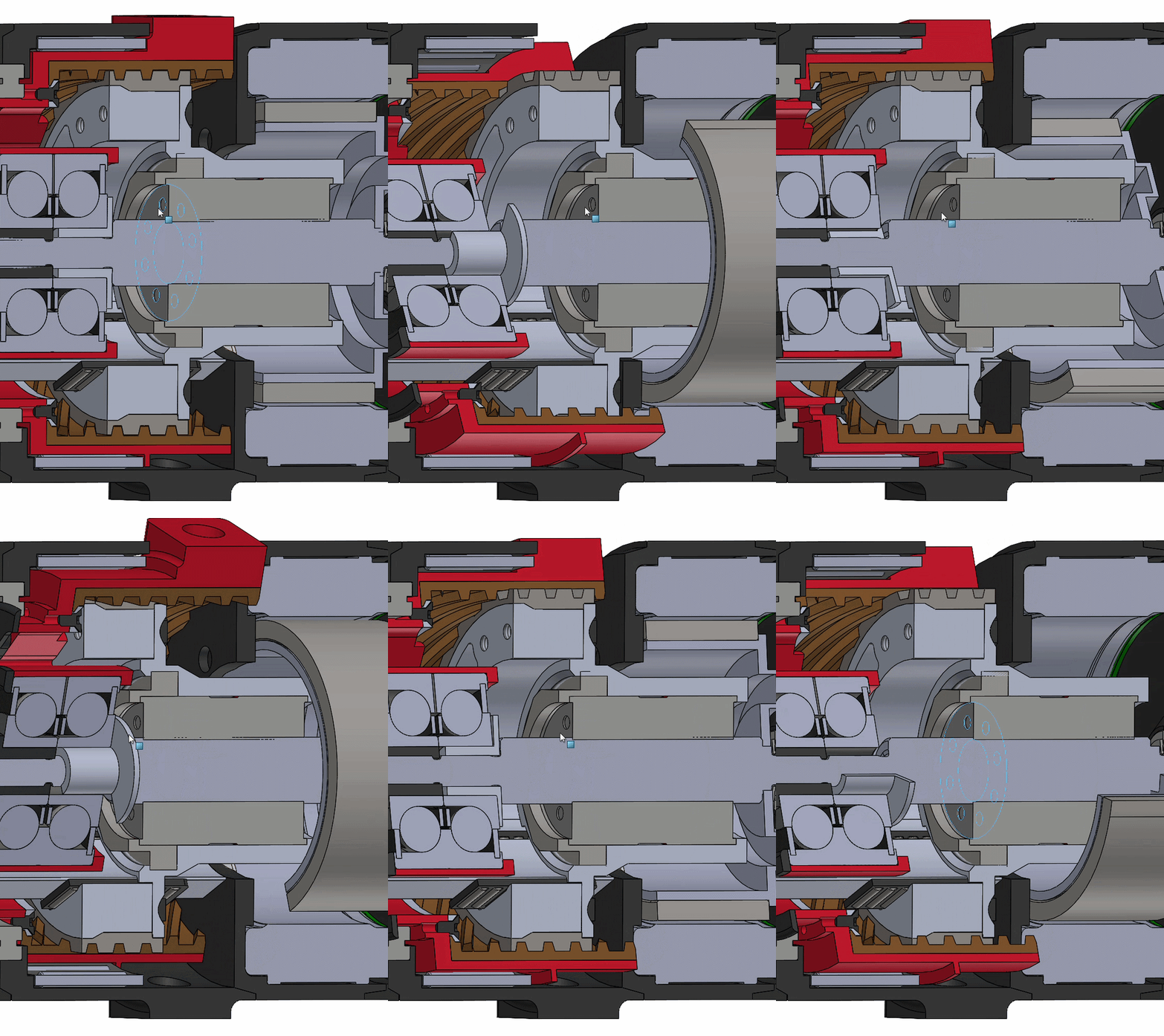
The differential elastic actuator. (a) Renders of the assembled
prototype and a cross section view illustrating the location of the spring.
(b) Exploded render with major components called out.

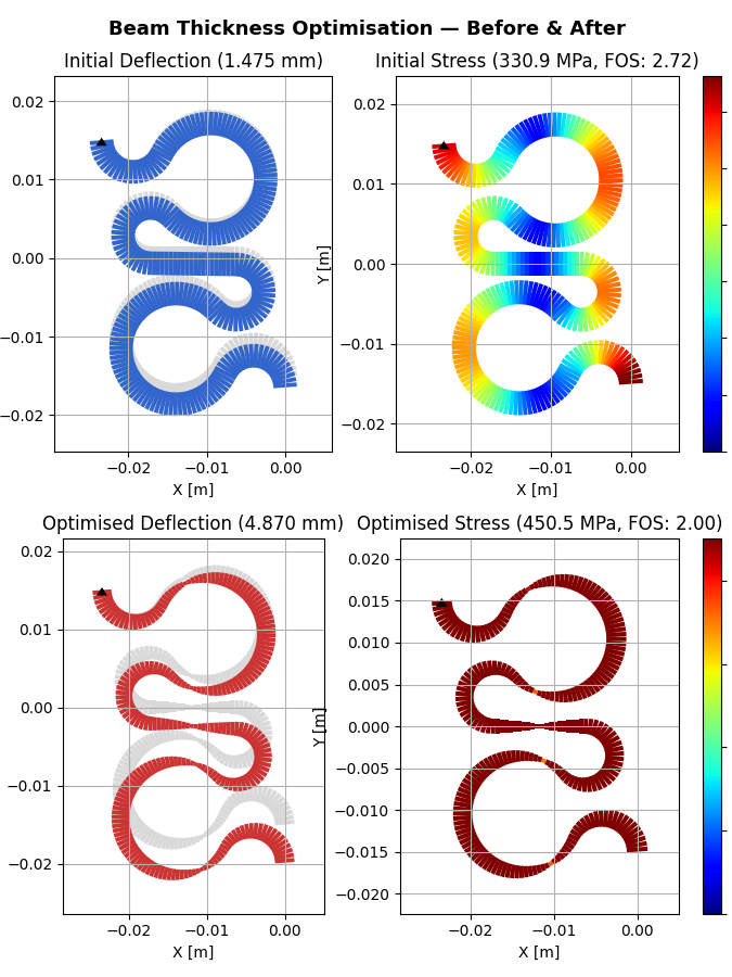
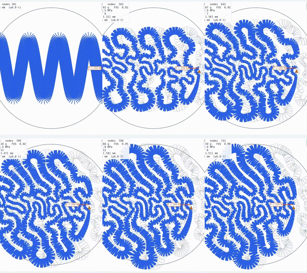
Geometrically nonlinear frame FEA and the equal-stress optimization loop.
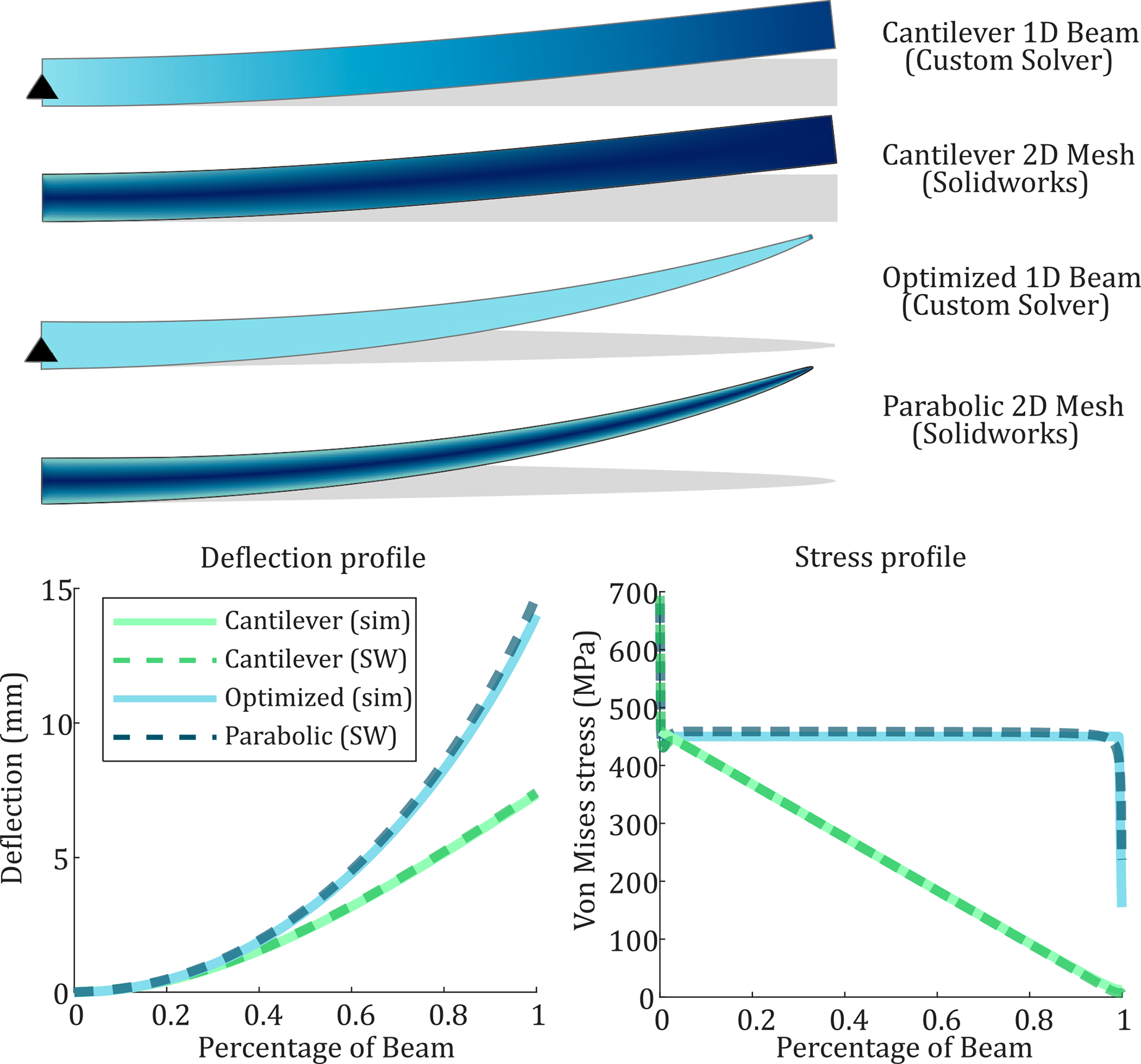
FEA and optimizer validation. A uniform cantilever, the same cantilever after equal-stress optimization (converging on the analytic parabolic, constant-stress profile), and the closed-form parabolic beam, with deflection and stress plots validating the one-dimensional optimizer. The solver matches the closed-form cantilever to 0.78% deflection RMSE and the optimized beam matches the analytic parabola to 1.76%.
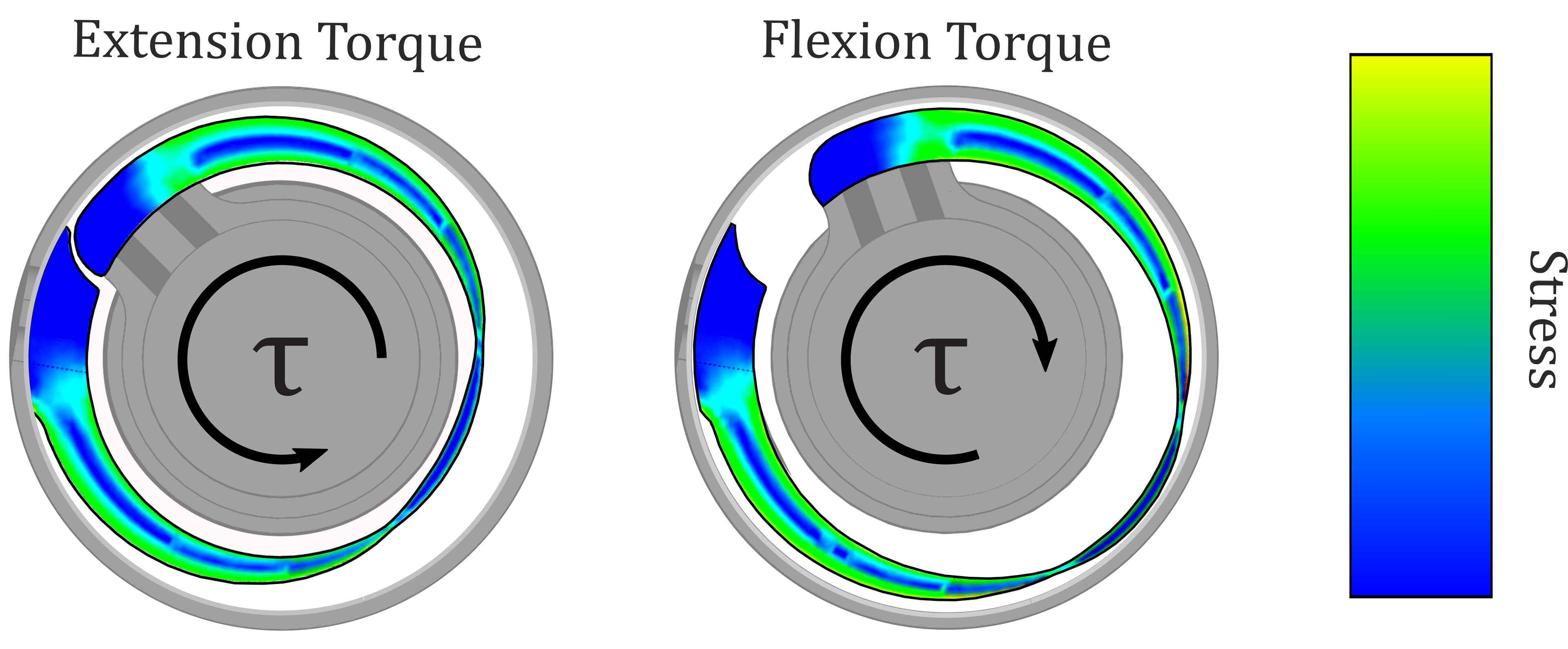
The optimized arcuate spring deflected inside the actuator housing,
showing the spring bottoming out against the housing walls within the
cylindrical envelope.
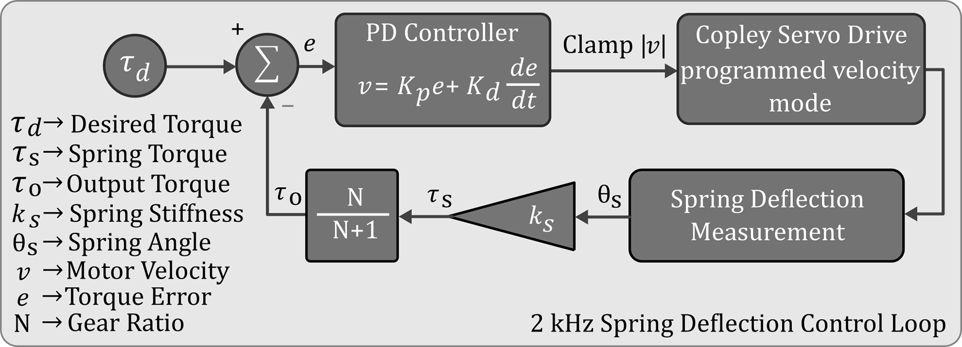
Velocity-sourced PD torque-control loop. The spring deflection
angle is measured, converted to an equivalent output torque, and then
compared to the desired torque to obtain a torque error. This error is driven
to zero with a PD velocity controller.
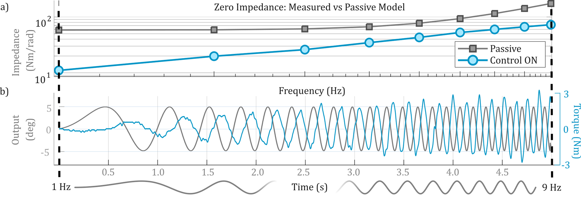
Disturbance-rejection bandwidth. Top: output impedance versus frequency, with and without the control loop active (comparing to a passive model that includes reflected inertia and backdrive torque). Bottom: torque response to an output-side chirp swept from 0.1 to 9 Hz over 4 seconds at ±5◦ (10◦ peak-to-peak). With the loop active, backdrive torque stays under 3 Nm across the full tested range, below the control-off case.