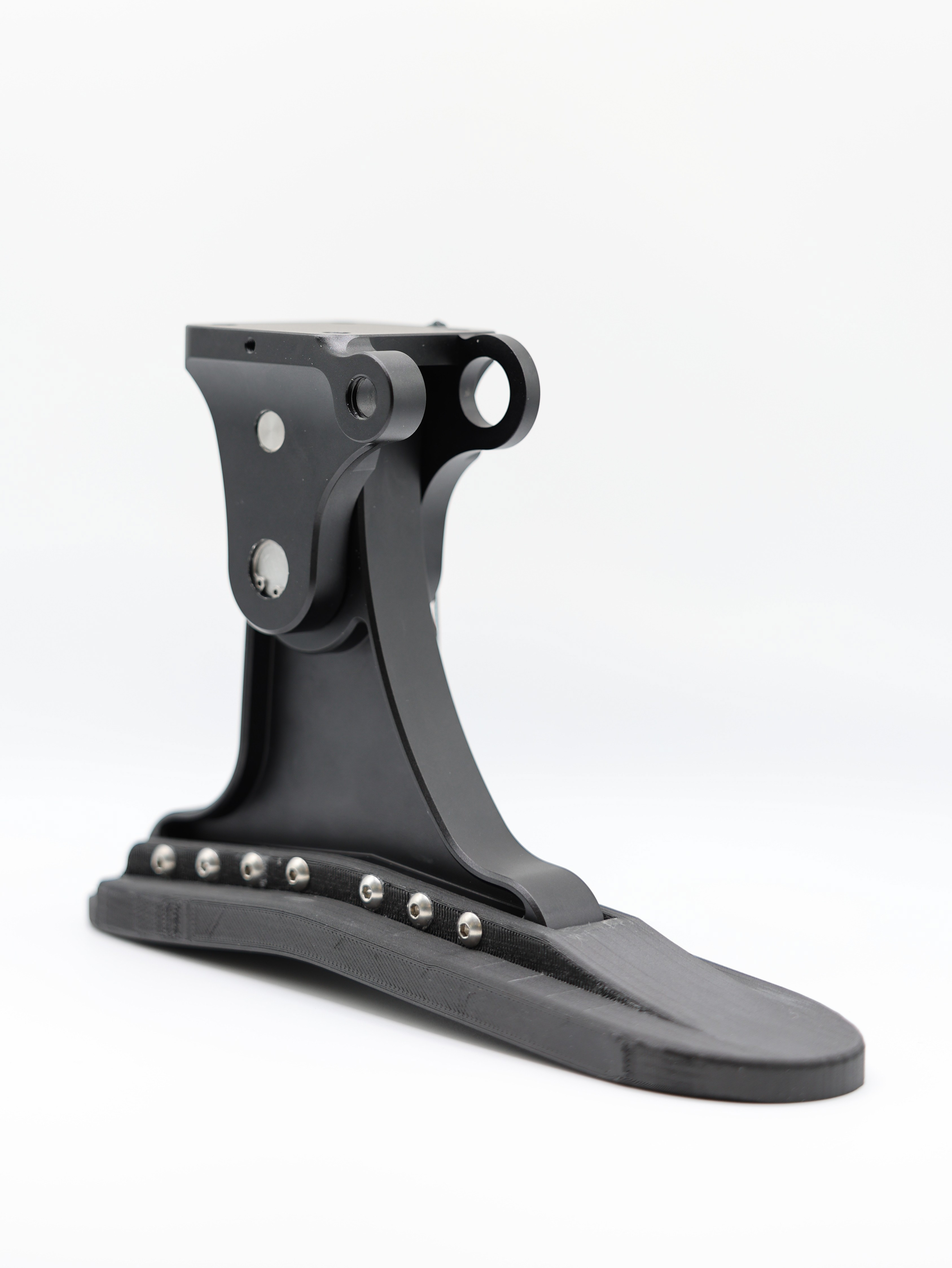
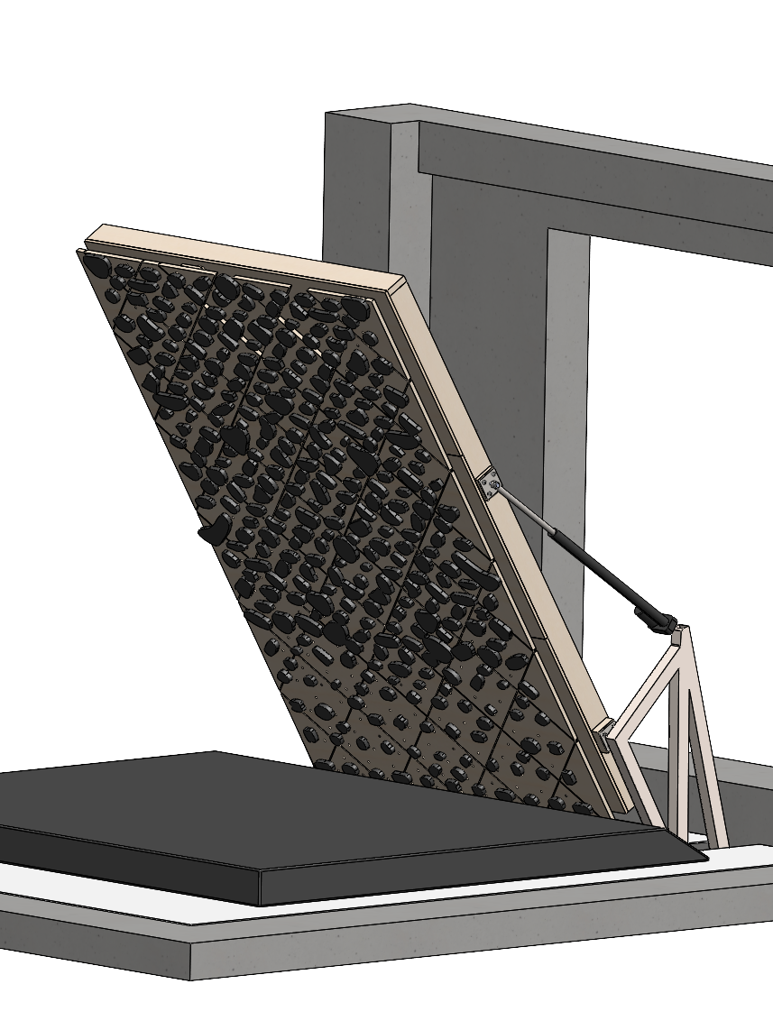
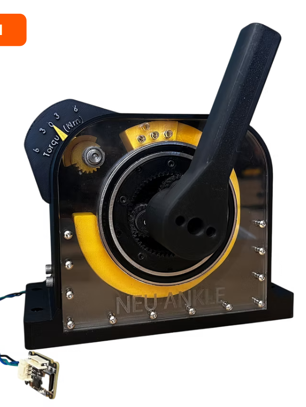
Powered lower limb prosthetics are powerful and connected to the human body, meaning that they can seriously injure the wearer during a serious controller malfunction. For instance, if the high-level finite state machine misreads the gait phase, treating early stance (which should absorb energy) as late stance (which should inject it), the device pushes when it should brake and pumps energy into the leg. Additionally, because weight is generally minimized, a small motor must perform at absolute thermal limits, and a controller that does not take this into account can destroy the actuator. The usual answers are conservative gain tuning and hard current saturation, which give no formal guarantee and cost performance even when nothing is wrong. This project, completed for ME 7374 (Safe Control & Estimation) at Northeastern, instead treats both failures as safety constraints and builds a control barrier function (CBF) safety filter that sits between the nominal torque controller and the motor.
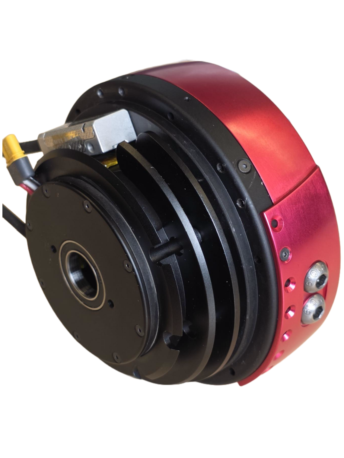
The plant is a series elastic actuator ankle: a brushless motor through a 50:1 gear train into a 600 Nm/rad output spring, with spring deflection measured and used for closed-loop torque control. Motor parameters come from an ILM 50x14 frameless kit (0.103 Nm/A torque constant, 0.77 ohm winding resistance, 5.3 A continuous rated current), giving 27.3 Nm of rated output torque against a reflected output inertia of 0.051 kg m^2. Coil temperature is a single lumped node with 7.47 J/degC capacitance and 1.5 W/degC convective loss to 25 degC ambient, limited to 120 degC by the winding insulation. The reference is biological ankle angle, velocity, and moment from level treadmill walking at 0.9 m/s, resampled to 10 kHz and converted into a spring deflection command through the SEA kinematics. The full model is five states: output position, output velocity, integral error, coil temperature, and tank energy.
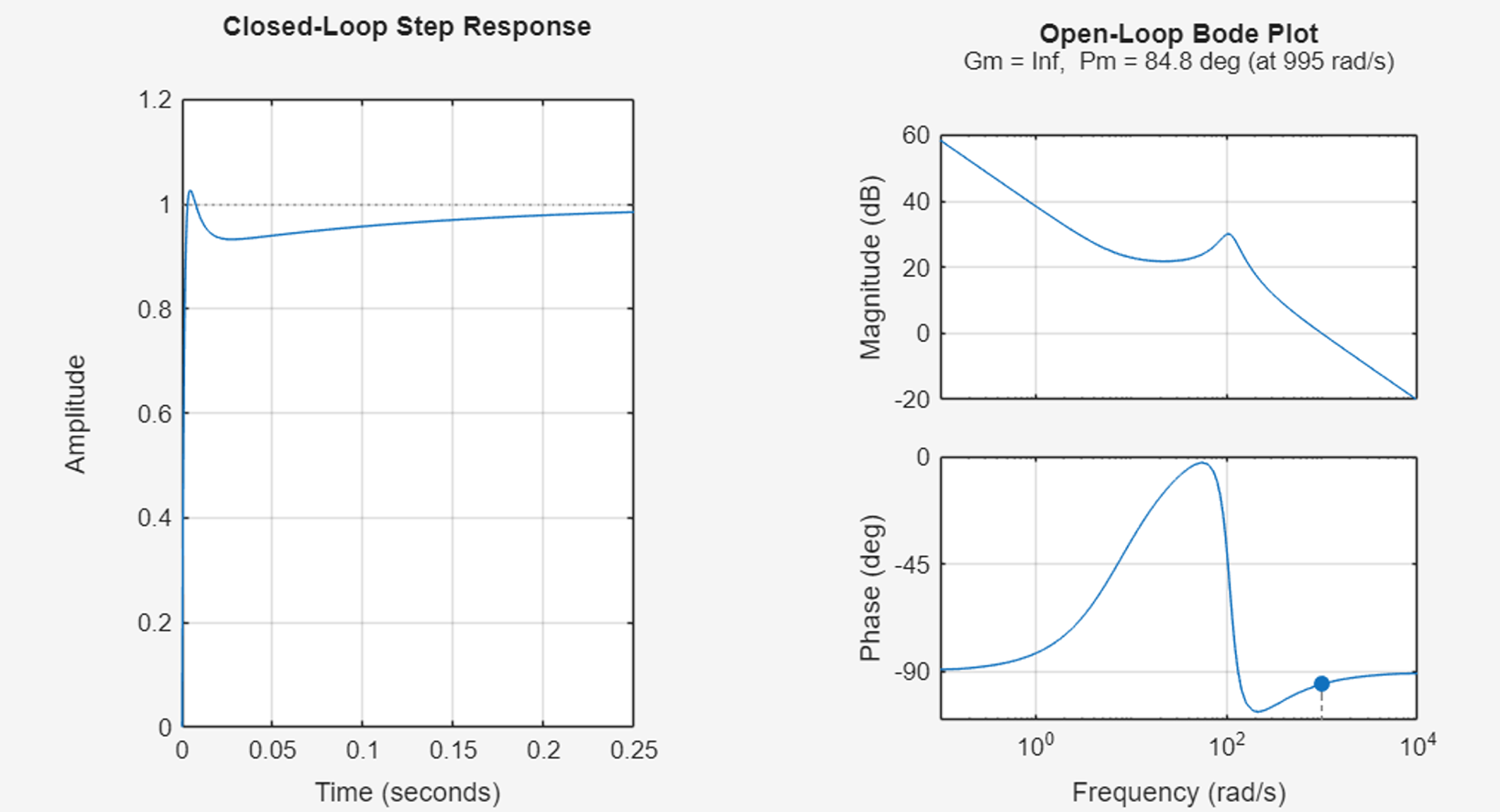
Closed-loop step response (left) and open-loop Bode plot with gain
and phase margins (right) for the nominal PID controller and SEA plant.
For thermal modeling, we define the barrier as h1 = Tmax minus coil temperature, the motor current enters the temperature dynamics directly through Joule heating, so h1 has relative degree one and the CBF condition can be solved in closed form rather than by calling a solver. Because current enters as a square, the condition collapses to a symmetric torque envelope whose width is set by a thermal margin combining the convective term and the current barrier value, so the envelope tightens smoothly as the coil heats and throttles the motor before the limit rather than at it. Feasibility never fails: on the barrier boundary, where the coil sits exactly at 120 degC, the margin reduces to the strictly positive convective term, so zero torque always satisfies the constraint and the safe set cannot become empty. Closed-form evaluation also means the filter costs a square root and a saturation per timestep, which is a reasonable thing to put in an embedded control loop.
Thermal barrier h1 = Tmax − Tcoil during normal walking. The
barrier remains positive under the CBF safety filter, confirming forward
invariance of C1.
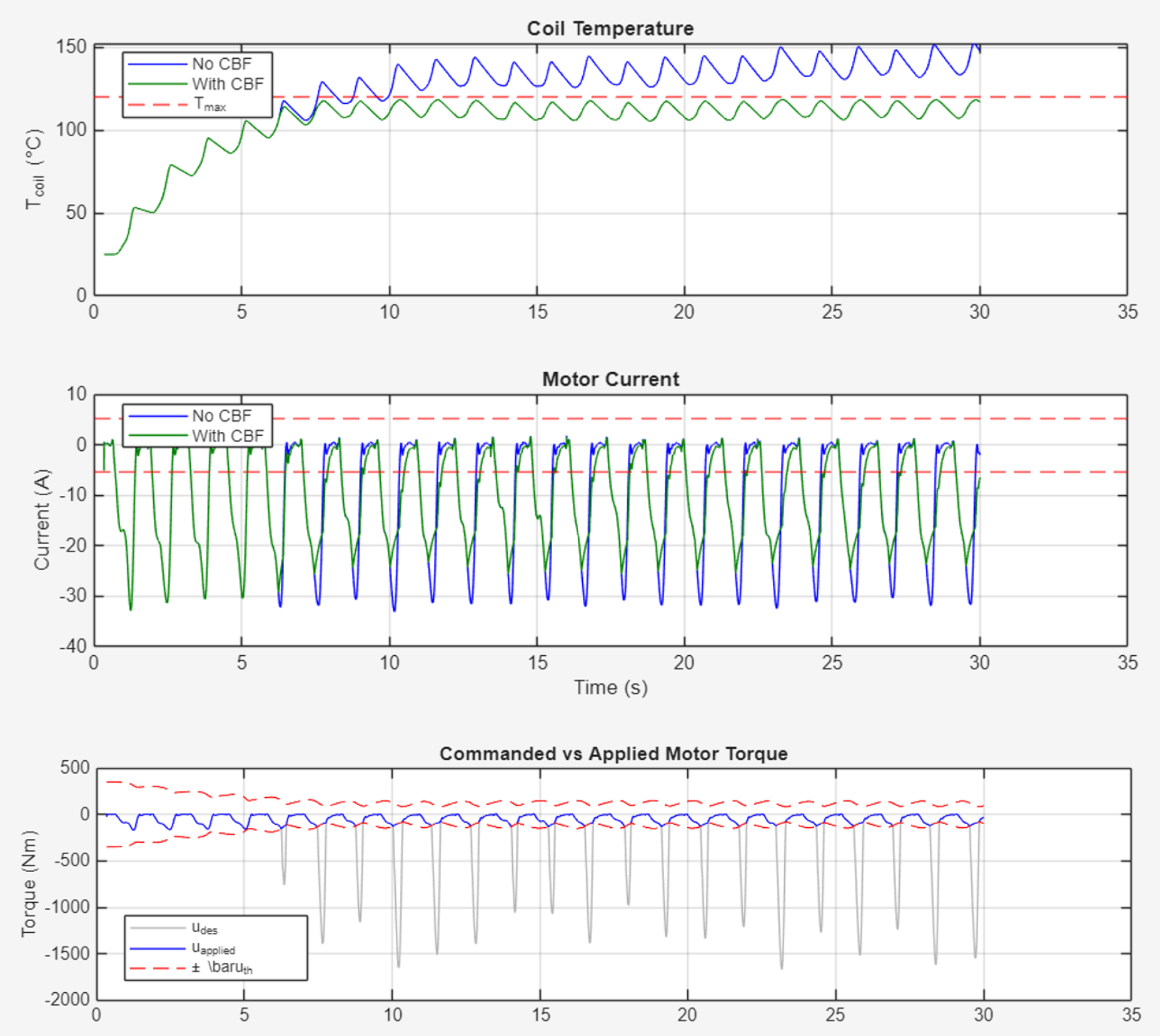
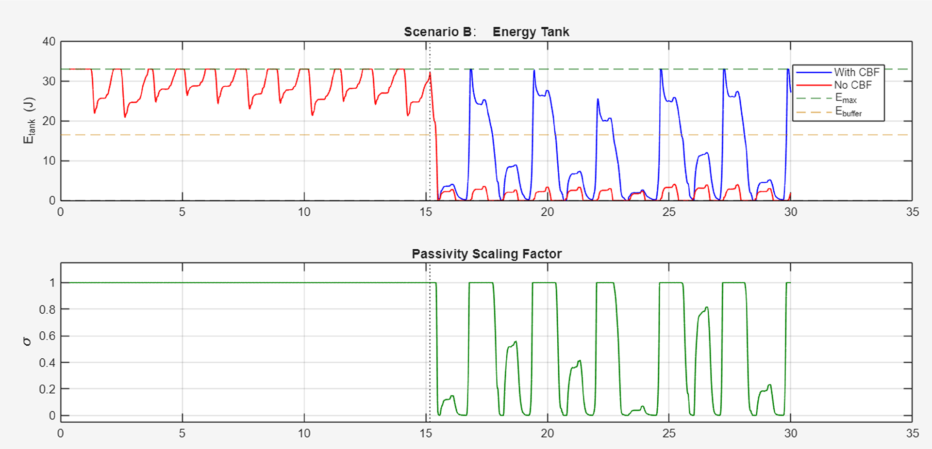
Passivity was harder and is where most of the work went. The natural barrier is the energy tank level itself, a virtual reservoir that charges when the device absorbs energy from the user and discharges when it injects. The problem is that tank energy is relative degree three in motor torque, and the required Lie derivatives are dominated by ankle jerk, which reaches roughly 7000 rad/s^3 in the measured gait data. A formally correct third-order CBF built on that signal demands extreme control effort and destabilizes the loop, so it is not usable here. Instead I enforced the same invariance property with a cubic smoothstep scaling on the commanded torque: as the tank drains toward a buffer threshold, a factor between one and zero attenuates any command that would inject energy, and at an empty tank the factor is zero, the motor goes passive, the spring relaxes toward zero deflection, and injection stops on its own. Tank capacity is sized as a multiple of the per-stride energy swing measured from the unconstrained run, which is the knob that trades safety margin against how often the filter intervenes. We command a torque profile that violates the passivity constraint and observe the behavior of the filter. As can be seen, the case with no CBF continues to command large energy expenditures, while the case with the CBF keeps energy output to a minimum.
Normal walking comparison. Top: coil temperature with and without
the CBF (dashed line indicates Tmax = 120 °C). Middle: motor current.
Bottom: commanded vs. applied motor torque with thermal bounds ±¯uth.
Finally, we need to test both fault scenarios simultaneously. The fault scenarios inject a finite state machine misclassification at the trial midpoint, negating the torque command whenever the nominal controller would have absorbed energy, so every braking phase becomes an injection phase. In the passivity-focused fault the tank is deliberately sized small so it can drain within a few gait cycles. The unconstrained controller empties it within roughly one stride of fault onset and holds it at the floor for the rest of the trial while continuing to demand injection, and it also heats the coil to 150.2 degC. The filtered controller ramps the scaling factor down as the tank approaches zero, holds the minimum tank level at numerically zero without a meaningful violation, recharges on each subsequent absorption phase, and stays at 86.2 degC because the attenuated command draws far less current, with tracking RMSE rising from 18.74 to 50.35 Nm. Without the filter the coil runs to 414.9 degC, while the filtered case holds 119.4 degC.
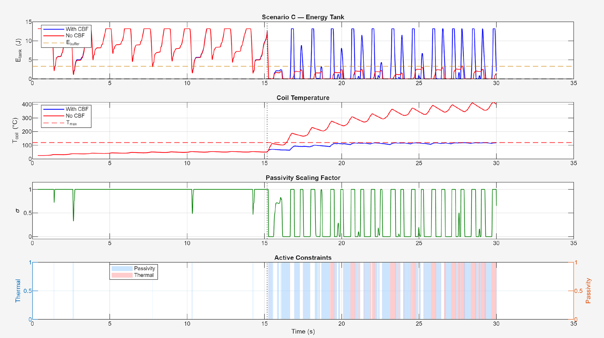
Scenario C (combined fault). From top: energy tank, coil temperature, passivity scaling factor, and active constraint indicators.
There are some obvious problems with this. First, that an FSM misclassification is usually an issue with a higher-level controller, and if you have a higher-level controller that is allowed to select for level ground or stair descent, it's just as likely to misclassify stair descent as level ground walking and not inject enough energy during walking, creating a separate risk. While I think the energy tank concept is interesting as a safety metric, it might be more realistic to have it as a higher level "safety stop" that only really registers serious control law failures and steps in to shut the system down. I saw this project more as an interesting deep dive into some fairly complicated controls, and in that respect I feel that I learned a great deal.