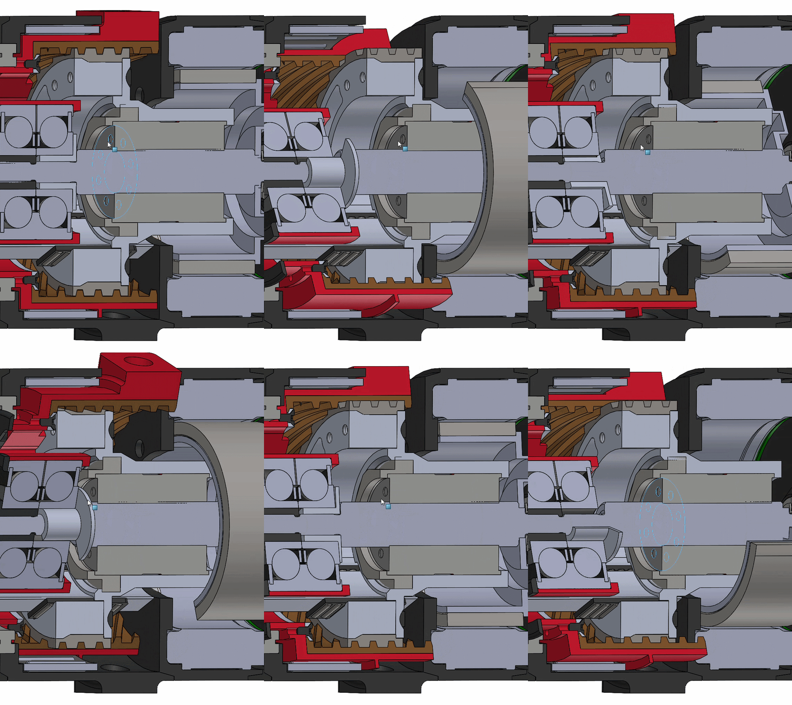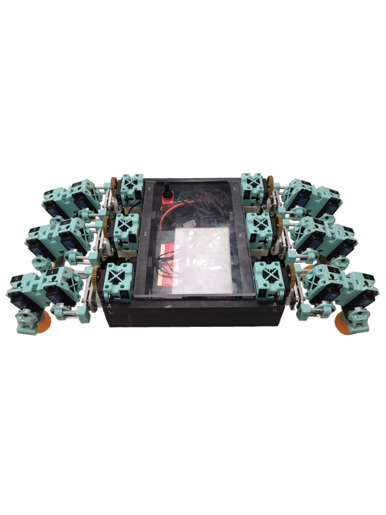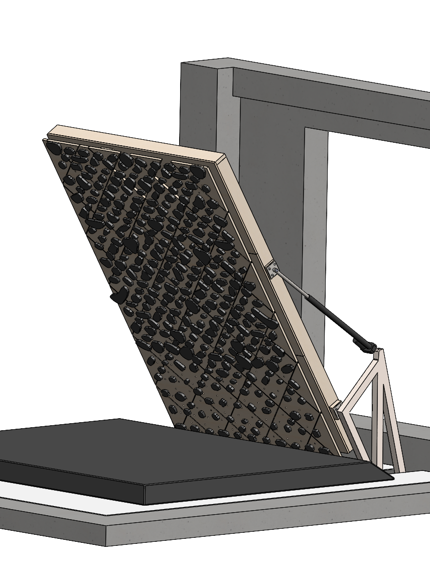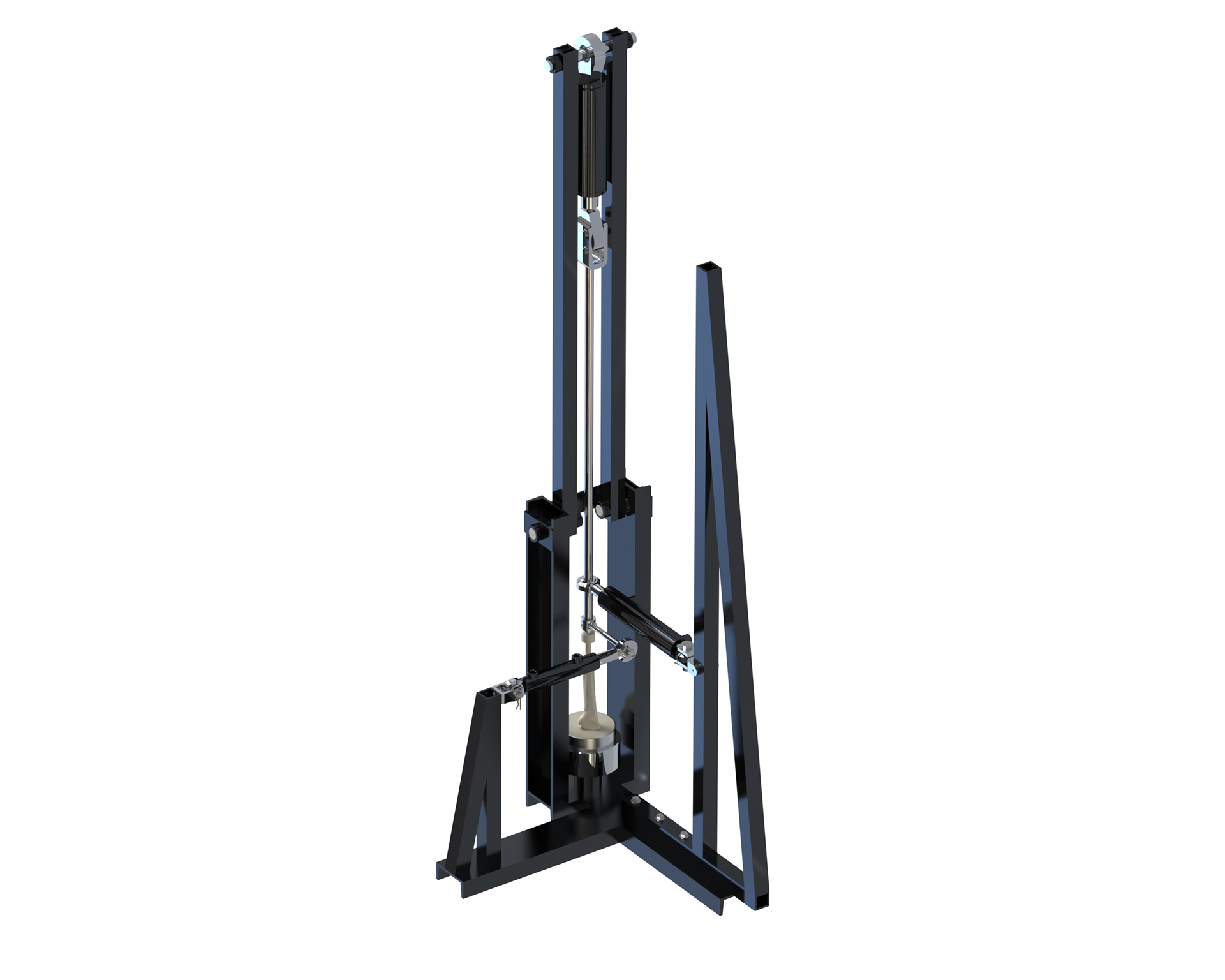
The work outlined below is detailed in Grant Award OR240098, which has been funded for $750k. My contribution to this project was the design of the bone mechanical strength characterization platform, which is currently being fabricated by another student. The figures below are from the grant.
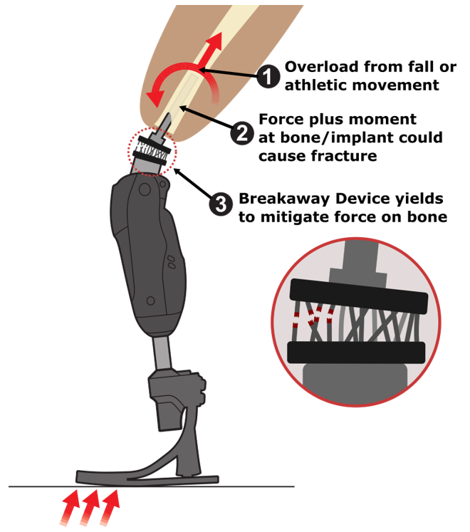
Osseointegration replaces the traditional prosthetic socket by anchoring the limb directly to the residual femur through a titanium implant. It restores mobility, proprioception, and comfort, but it introduces a new failure mode: because the prosthesis now attaches straight to the bone, a hard impact, an awkward landing, or a fall transmits that load directly into the femur and can fracture it. To stay safe, patients are currently told to avoid the very high-activity movements osseointegration was meant to give back to them.

Operating Principle of an OI Breakaway Device. When large forces are induced on the foot, large forces and moments are transferred to the bone-implant interface. To prevent dangerously large loads, a “Breakaway Device” mechanically decouples the prosthetic leg from the abutment and residual limb.
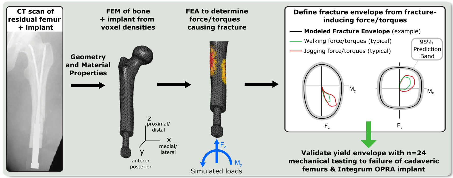
This project develops a patient-specific breakaway device, a mechanical fuse placed in line with the prosthesis that yields and disconnects before the bone can break, much as an electrical fuse blows before a circuit is damaged. Doing this well requires knowing, for each patient, the precise combination of forces and torques their femur can withstand. Because loads on the limb act across all six degrees of freedom at once (three forces and three moments), that safe boundary is a six-dimensional fracture envelope, not a single number. The project predicts each patient's envelope from a CT scan and finite-element model, then uses design optimization to generate a single-use titanium fuse tuned to yield just inside it.

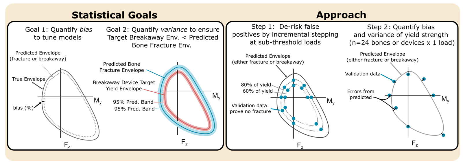
Aim 1 Overview.  A Finite Element (FE) model will be constructed from Computed Tomography (CT) scans of the femur, with bone geometry and material properties estimated from voxel densities. A series of combined force/torque loads will be applied to the FE model to calculate the fracture envelope (the boundary of loads the bone can safely withstand) in three sub-planes of force/torque space (only two shown). Finally, 24 cadaver femurs with be surgically implanted with the OPRA system, and will be loaded stepwise in an in-house material testing system to validate the fracture envelope and to characterize the prediction band. (Scan, FE model, and walking/running biomechanics modified from Pierro 2021; Winson 2008)
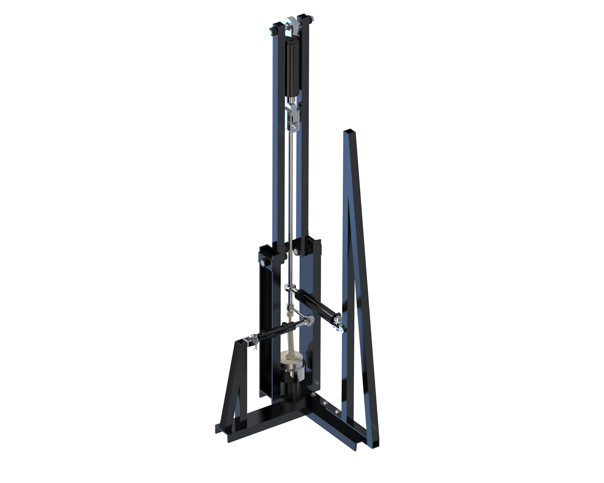
A predicted fracture envelope is only trustworthy if it is validated against real bone, and that is the role of the test fixture I designed. It grips a cadaver femur fitted with the osseointegration hardware and loads it to failure under controlled combinations of force and torque, reproducing the multi-axis conditions a real fall or maneuver would create. Without a large robotic arm, independent 6-DOF testing cannot be done. However, such an arm would be prohibitively expensive, so the jig replicates 6-DOF with three independent hydraulic pistons.
The three independent hydraulic pistons are shown in the render to the right. For a 6D envelope, it is important to be able to apply combinations of forces F_x, F_y, and F_z, and moments M_x, M_y, and M_z. 
1. The large piston at the top handles F_z, applying large compressive or tensile loads on the femur implant. The whole piston assembly is allowed to rotate slightly when large loads are applied, ensuring that F_z is applied in the frame of reference of the implant even under significant deflections and that the off-axis forces (which hydraulic pistons do not handle well) are minimized without the need for additional fixturing.
2. The middle piston applies F_x, F_y, and M_x, M_y. Firstly, by converting X and Y to cylindrical coordinates, the number of loads and moments can be reduced to F_r and M_r, simple vector combinations of X and Y. Secondly, the piston is adjustable in the vertical direction. Close to the bone, very large forces applied at a very small moment arm will result in a proportionally tiny moment, simulating a pure F_r force. Far from the bone, very small forces will generate proportionally huge moments, simulating a pure M_r moment. By carefully selecting a distance for the piston to apply a force, a virtual combination of M_r and F_r can be applied. In this manner, the single piston applies 2 loads and 2 moments.
3. The bottom piston is attached directly at the implant and applies the M_z moment, forcing the implant to screw or unscrew from the femur.
In operation, many femurs will be placed in the device and load combinations will be applied to determine the fracture envelope of different femur geometries, which may be extrapolated to patient agnostic, geometry based load limits.

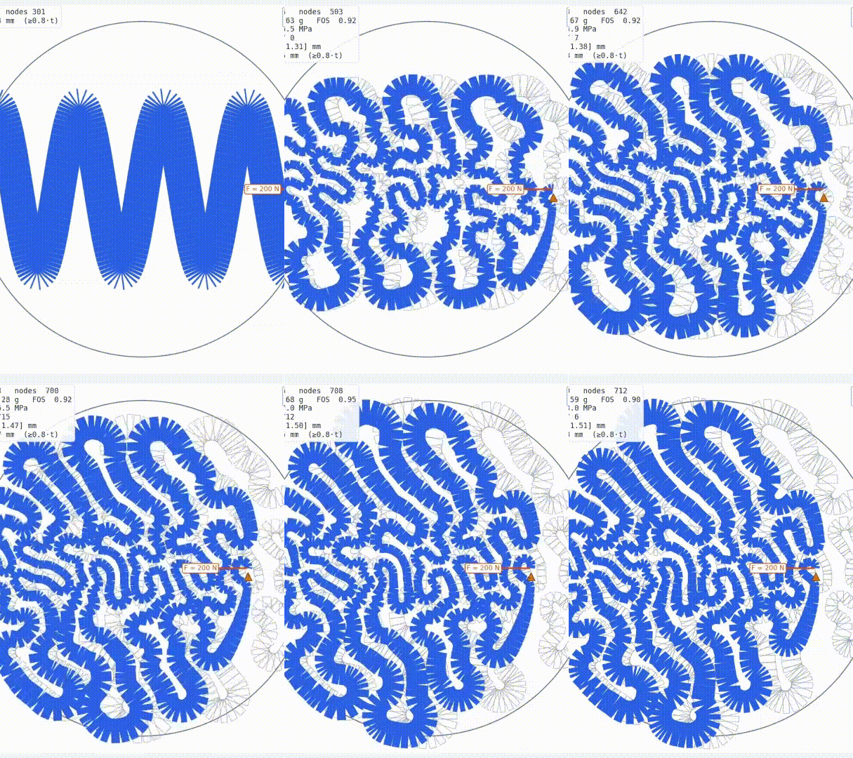
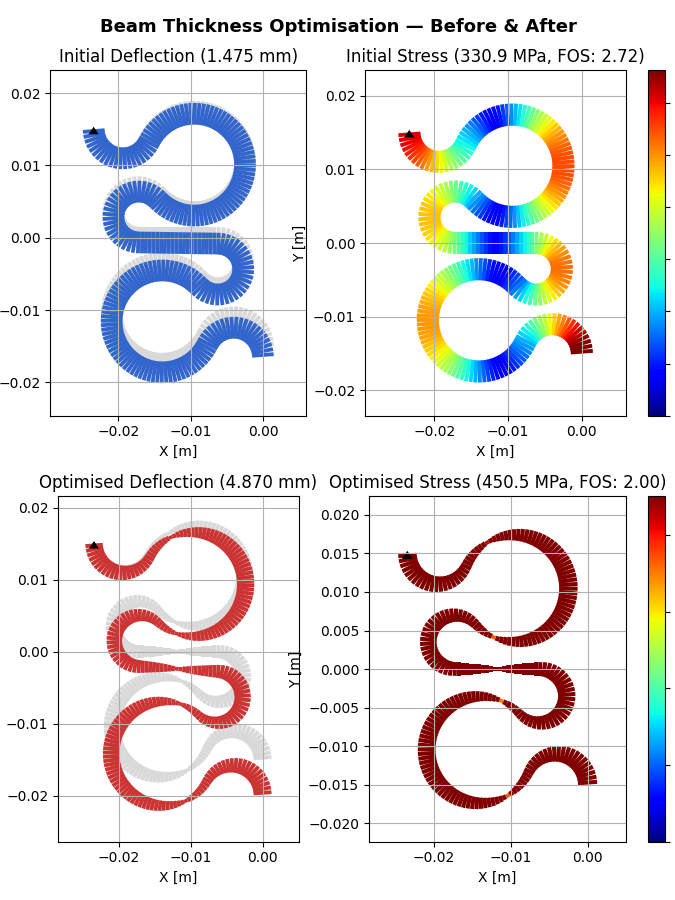
Aim 2 Overview. The Breakaway Device’s target yield envelope will be initially defined as 90% of the modeled fracture envelope (note: this fixed percentage will be replaced post-validation by the characterized 95% prediction bands, as described in the Statistical Analysis section). Loads will be selected from the target yield envelope to be applied during the optimization. The mathematical optimization then modifies the shape of the part (in this optimization example, only the diameter of parameterized columns) until the part yields when the loads on the Yield Envelope are reached, for all tested loads on the target yield envelope (only one load illustrated).  After a suitable shape has been found for a nominal target yield envelope, the parts will be 3D printed using a metal printer and tested for validation using the custom 6-axis material testing system.
Together, the modeling and the validated hardware turn a blanket "avoid high-impact activity" restriction into a quantified, personalized safety margin. The long-term goal is to let people with osseointegrated limbs run, jump, and recover from falls without risking a periprosthetic fracture.

You may also like

Back to Top